RE PFL
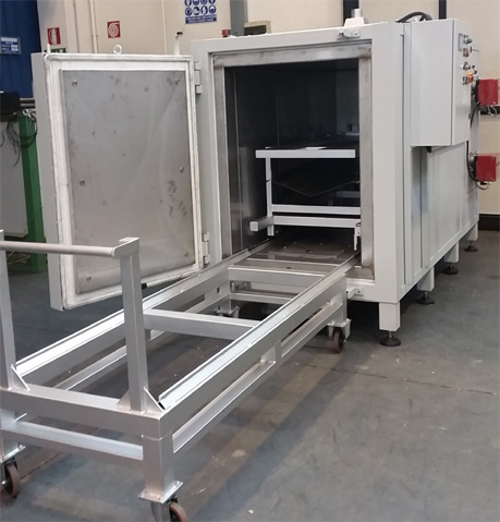
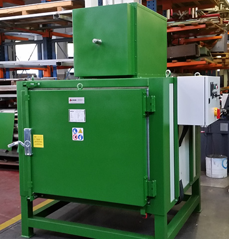
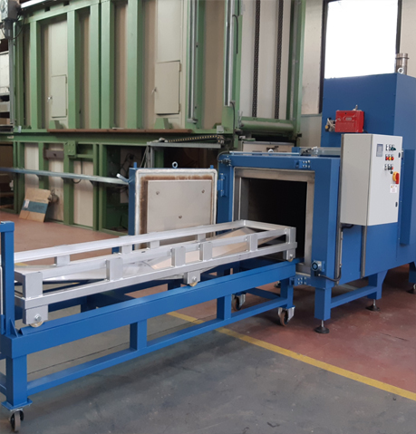
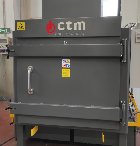
INDUSTRIAL CHAMBER OVEN
Our company, to complete the range of products for the pyrolysis process, introduces two models: RE PFL and RE PF.
In both cases, the operation of these furnaces in the cleansing of filters and die plate packs is based on the process of "PYROLYSIS" according to which the hydrocarbon molecules, less stable if subject to heat, when subjected to certain thermal cycles, break (cracking) giving rise to simpler gaseous molecules.
In our case the pyrolysis obtained from the polymer which coats the parts, while a complete incineration process is realized, generates combustible gases which are subsequently brought to complete oxidation in the post-combustion chamber generating products perfectly suitable for release into the atmosphere.
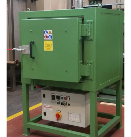
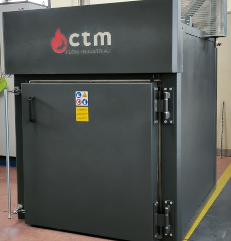
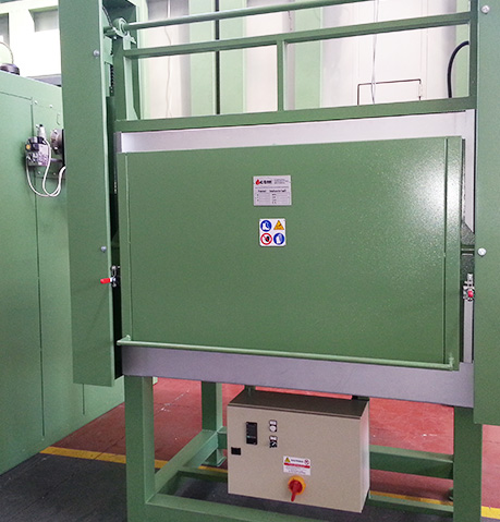
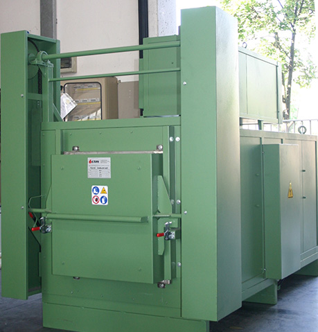
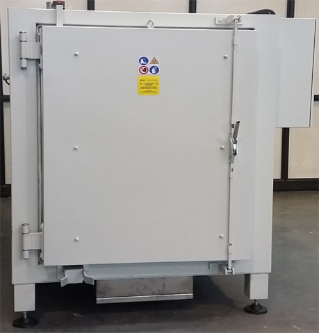
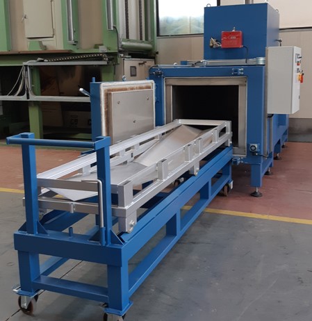
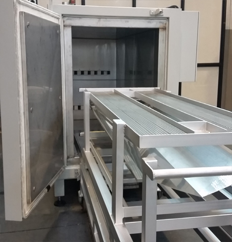
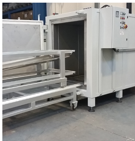
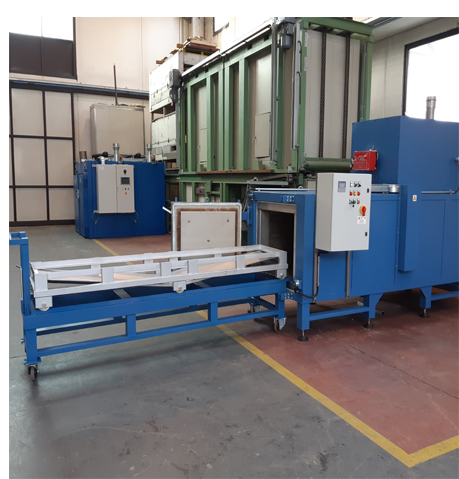
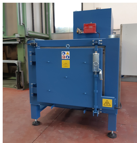
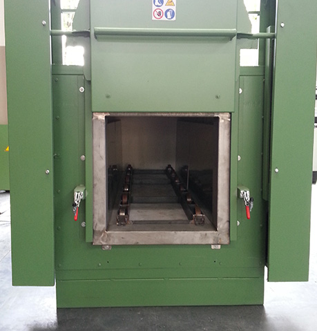
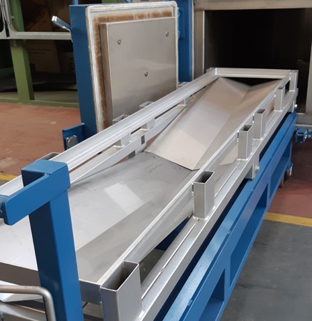
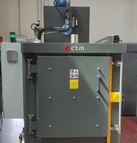
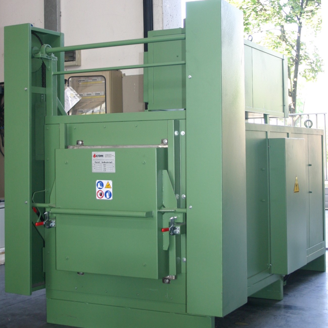
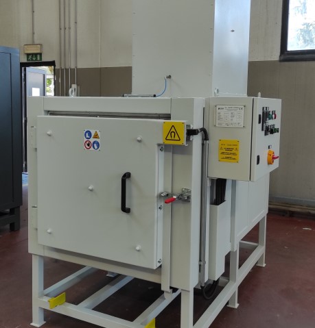
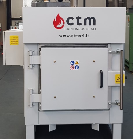
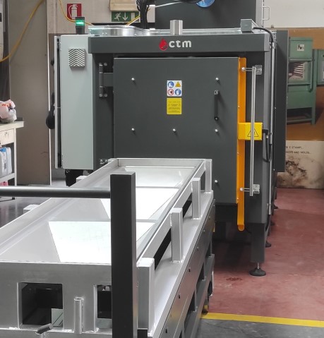
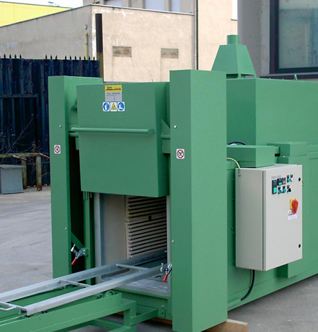
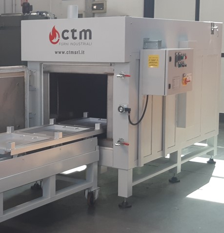
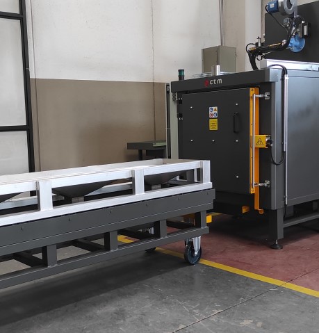
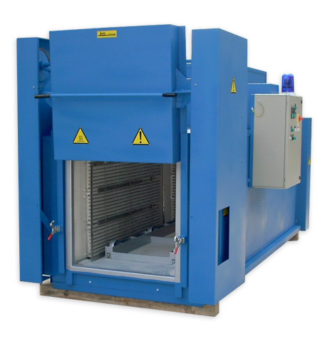
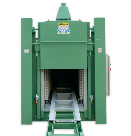
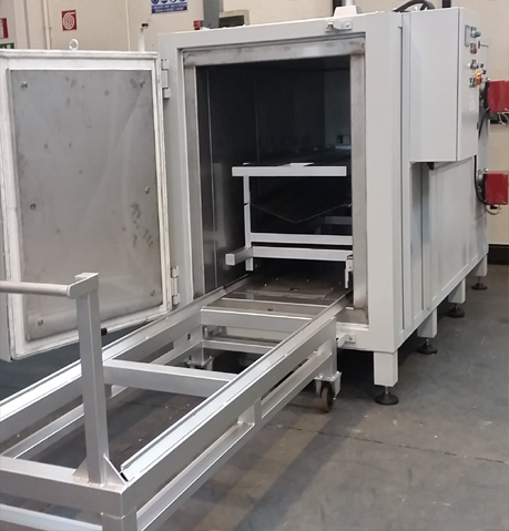
For pyrolysis processes that require significant functional dimensions of the chamber, CTM has designed the model RE PFL. Structurally, as for the model RE PF of smaller size, it is constructed with walls of stainless steel sheet.
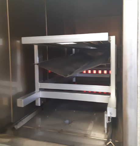
Heating, depending on the product to be treated and its size, will be established with our technical staff. Usually this can be either direct or indirect through the use of sets of electrical resistances. The choice will also determine the feasibility study on the positioning of the stacks for flue gas removal.
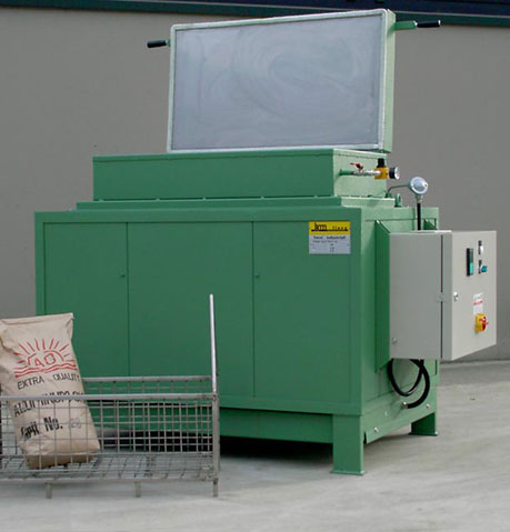
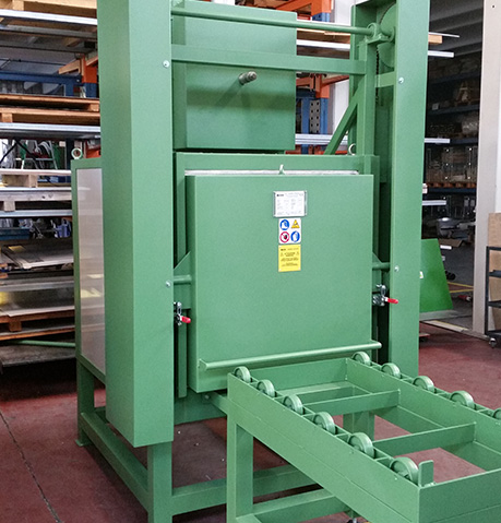
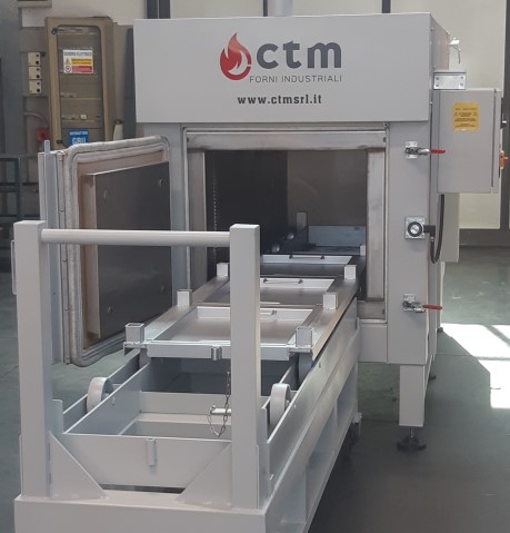
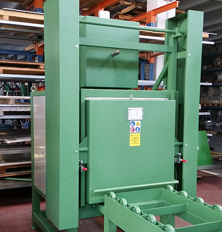
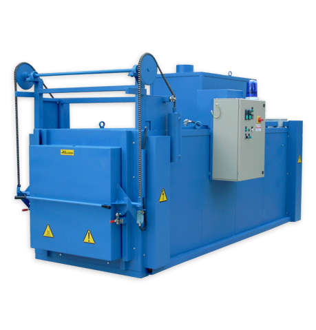
Door opening: with hinge or counterbalanced guillotine with manual or servo-assisted handling system.
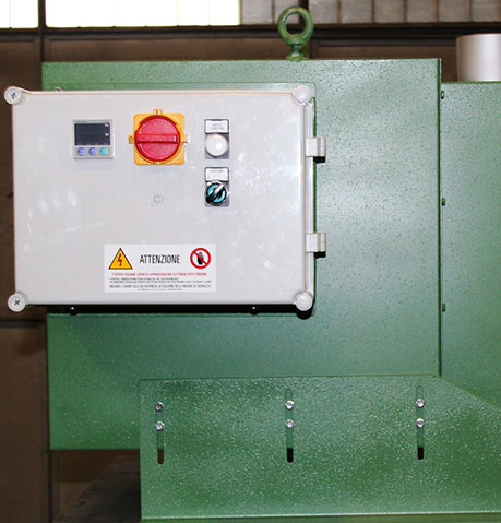
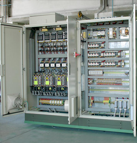
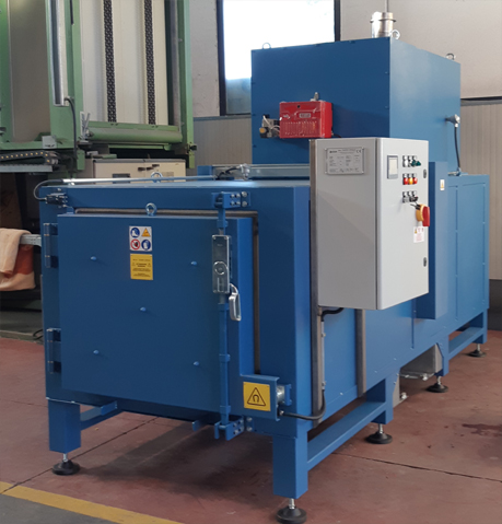
- Electronic adjustments of temperature through static power relays with the possibility of programming and data logging.
- Flue gas stacks with the possibility of direct connection to post-combustion chamber.
- Pyrolytic treatment in reducing atmosphere
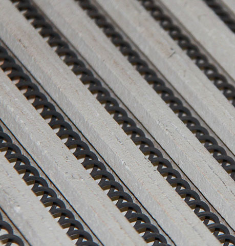
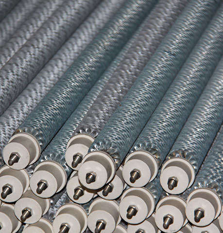
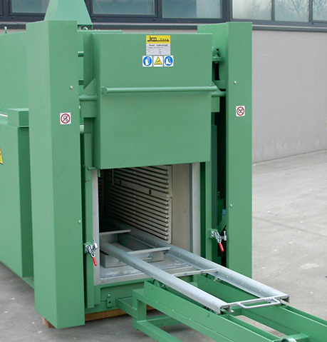
- Cleaning of packs and die plates
- Cleaning of filters
- Cleaning of extrusion screws
Post-combustor.
Hood positioned on the door.
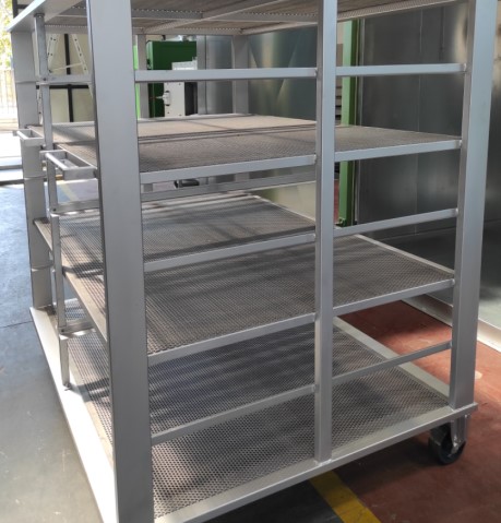
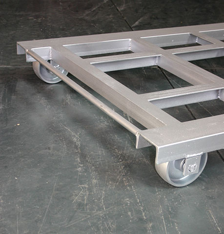
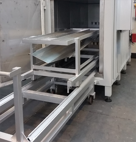
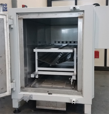
Dollies with mobile or fixed shelves in stainless steel sheet.
Specific equipment for individual needs.
| Model RE PFL |
Useful dimensions of the chamber | Rated power | Capacity | ||
| Width | Height | Depth | Kw | Lt | |
| RE PFL/1 | 500 | 500 | 2000 | 24 | 500 |
| RE PFL/2 | 750 | 750 | 1500 | 30 | 840 |
| RE PFL/3 | 750 | 750 | 2000 | 35 | 1125 |
| RE PFL/4 | 750 | 750 | 2500 | 40 | 1580 |
| RE PFL/5 | 750 | 750 | 3000 | 45 | 1685 |
| RE PFL/6 | 750 | 750 | 3500 | 55 | 1970 |